Tips & Tricks for using Power Path
Power Path is a software solution that enables users to add and create their own custom models of poles and insulators. Last time we wrote about adding and creating a pole/tower model in Power Path. Read more about it in our blog post How to design a pole (tower) for power lines? How to use it in Power Path? Today, we will show you how to create and add a custom insulator data model in Power Path.
Besides all the commands for power line projects, Power Path also has commands for 2D drafting and 3D BIM modeling, so users can create any 2D/3D objects. Learn how to use additional CAD commands in Power Path for drawing and modeling in order to create a 3D model of the insulator:
3D models of insulators can also be created in CAD/BIM software solutions such as Tekla, SketchUp by Trimble, Autodesk Revit, Advance Steel, or any other kind of software that supports record of 3D models in .dwg or .ifc format.
To create and add a custom 3D model of an insulator certain rules must be met:
– Model must be defined in a separate .dwg file.
– ..dwg file should not have any other object in it (blocks, layers, entities), otherwise they will be imported as well.
– Model should not be saved as a block. If a block is imported from a different file explode it.
– Model should be placed on layer 0.
– Units should be meters. If different units are used, they will be denoted as meters.
– Insulator centerline should be placed in absolute zero (@0,0,0).
– Symmetry line should follow x-axis.
– Origin should be the point where the insulator would be attached to the support.
– Insulator should be rotated so conductor direction follow z-axis.
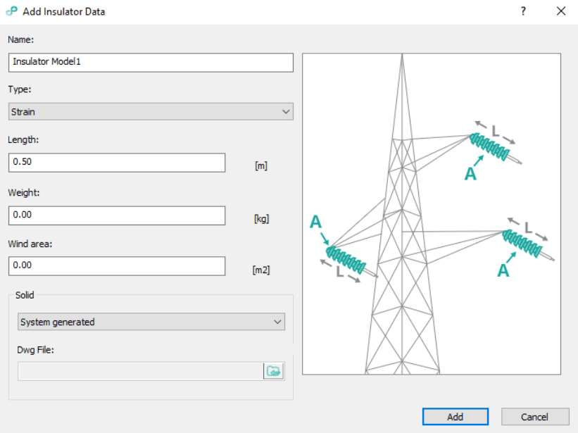
There are already several insulator models in software that users can choose but in order to import your own model or to use simple system-generated models, you must click on the command Add Insulator Data.
In the open dialog, you can define the name of the insulator,type (strain – for the tension supports, suspension – for the suspension supports, pin – for both suspension and tension supports, and clamp – special kind, for ground wires on both support types), length, weight and wind area. You then need to choose do you want to import your own model or you want to use simple system-generated models (displayed as 3D polylines). If you want to import a custom model of an insulator, you need to choose a Custom value from the 3D model section and import your drawing .dwg file.

Watch a step-by-step video tutorial and learn how to add insulator data in Power Path:
Feel free to try a 30-day free trial of Power Path and find out does Power Path fits your needs!

