After drawing the power line alignment, adding supporting poles and insulators (More about adding poles and insulators read in our blog posts How to design a pole (tower) for power lines? How to use it in Power Path? and How to create and add an insulator data model in Power Path?), the next step in the design of power lines is adding conductors and ground wires.
Follow this step-by-step tutorial to learn how to add conductor data in Power Path:
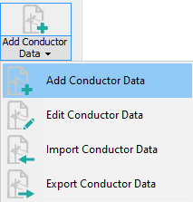
Click on the Add Conductor Data icon on the ribbon.

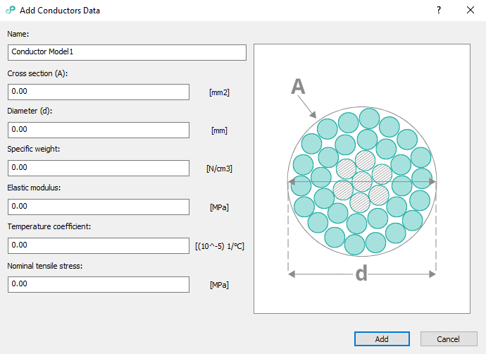
Add Conductors Data dialog will open.

You need to define next parameters:
– Name: unique value.
– Cross section: total conductor cross section.
– Diameter: equivalent conductor diameter.
– Specific weight: depending on the unit settings, either conductor weight per length divided by cross section or conductor weight per length.
– Elastic modulus: Young’s modulus of elasticity, measure of material’s stiffness, σ=ε·E
– Temperature coefficient: Coefficient of linear expansion per °C.
– Nominal tensile stress: Breaking load divided by cross section.
Click on the button Add to create a new conductor model based on the input.
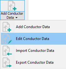
You can always edit your created conductor model by clicking on the Edit Conductor Data icon on the ribbon.

Your conductor model will appear in Project Explorer among other cables which are already implemented in the software solution:

Tip: For exchanging conductor models between your colleagues who also use Power Path, use the commands Import and Export Conductor Data. There commands will import/export conductor data in .xml file format. To learn what those .xml file should contain, read this article on our knowledge base – Appendix 4: Import/Export Conductor Data .
Now, you can use your created conductor model on your power line projects.
Click on the icon Add Conductor.

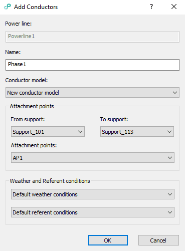
Add Conductors dialog will appear.

Options:
– Power line: power line name, read-only.
– Name: conductor name, it does not need to be unique.
– Conductor Model: a list of conductor data models.
Choose the model that you have created. In this case, that is New conductor model.
– From Support: name of the first tension support the conductor will be attached to.
– To Support: name of the last tension support the conductor will be attached to.
– Attachment Points: a list on attachment point names where the conductor can be attached to.
Note: only paired attachment points will be shown, e.g. if Support_101 has the attachment point named “AP1” all supports between it and Support_113 must have attachment points named “AP1”. For more details refer to our knowledge base – Appendix 2: Attachment Points on Support .
– Weather and referent conditions: weather and referent conditions models used to calculate catenaries parameters. By default, models chosen in the draw/edit power line will be used.
Click on the button OK to apply changes and add a conductor.

Feel free to try a 30-day free trial of Power Path and find out does Power Path fits your needs!

