Sometimes a picture is worth a thousand words, … or none. It is always important how you understand and watch it.
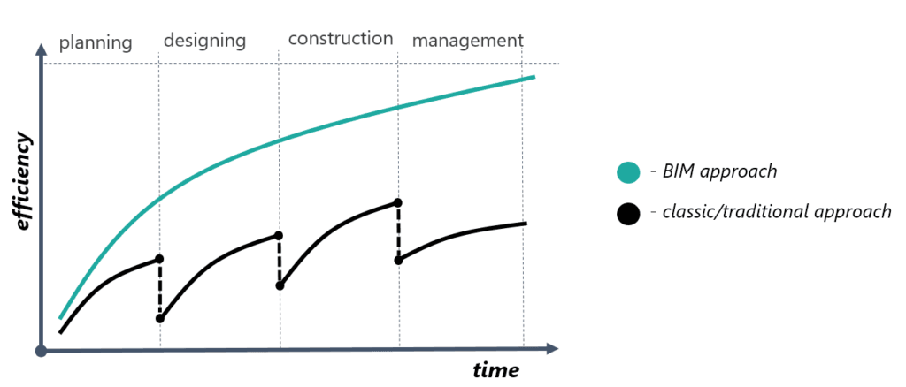
For us, these picture/chart present a reason why we created Power Path, a new software solution for power line design that can be used in different markets and requirements. For someone who is already involved in process of BIM (Building Information Modeling), which is a set of different technologies and processes, this chart is well known, but to be clear, let’s explain what is shown here and how it is related with Power Path solution. In explaining chart we will answer what is existing/traditional approach and can Power Path change it? How it is possible? Is it just important time and efficiency in object lifecycle or something else?
Let’s start from the beginning. In the lifecycle of each power line or other infrastructure object, first step is planning, then comes designing, construction and management. Usually, steps or phases of creating objects are fragmented and based on manual and semi-manual workflow. If we present it in short through the example it looks like this:
1. Planners suggesting the routes of power lines and reporting limitations.
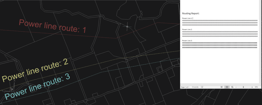
2. Then designers design the final route of the power line and provide the project to constructors.
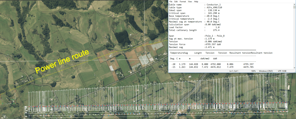
3. Constructors build the line on the created project and the power line is ready for use.
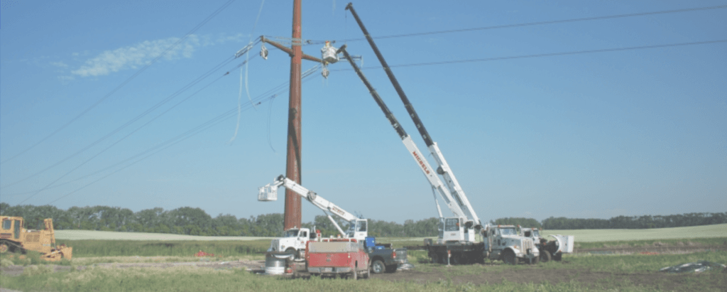
4. In the phase of management, investors monitor and maintain lines.

As mentioned, phases are fragmented and it’s normal in cases that different stakeholders (companies and teams) are involved in the same project. But it’s not normal and necessary to have fragmentation or restriction in information sharing, which is a problem in the existing approach of object lifecycle. It reduces efficiency, increases costs and time for collaboration.
With the Power Path solution we are moving forward from the classic (existing or traditional) to BIM approach in the lifecycle of power lines, so the solution is our answer to why we want to change the process in the design and next phases of power lines. The solution brings a unique format for sharing project information from the first to the last phase of the object lifecycle. Here are facts about why BIM approach speeds up process and increases efficiency:
- There are less information sharing restrictions through the developing 2D documentation and 3D BIM models in .ifc record (for better understanding just imagine ifc. format like .pdf format for construction), .dwg or .dxf formats.
- Increased project transparency in the design phase (time/schedule and cost i.e., 4D and 5D analyses are obtained from 3D BIM models and are dynamically linked) and reduced costs in next phases.
- Facilitation of project visualization enables effortless demonstration to clients and ensures full understanding of all project stakeholders.
- 2D design process enables the creation of necessary documentation (paper or electronic form) while 3D modeling enables advanced system elements modeling with additional information.
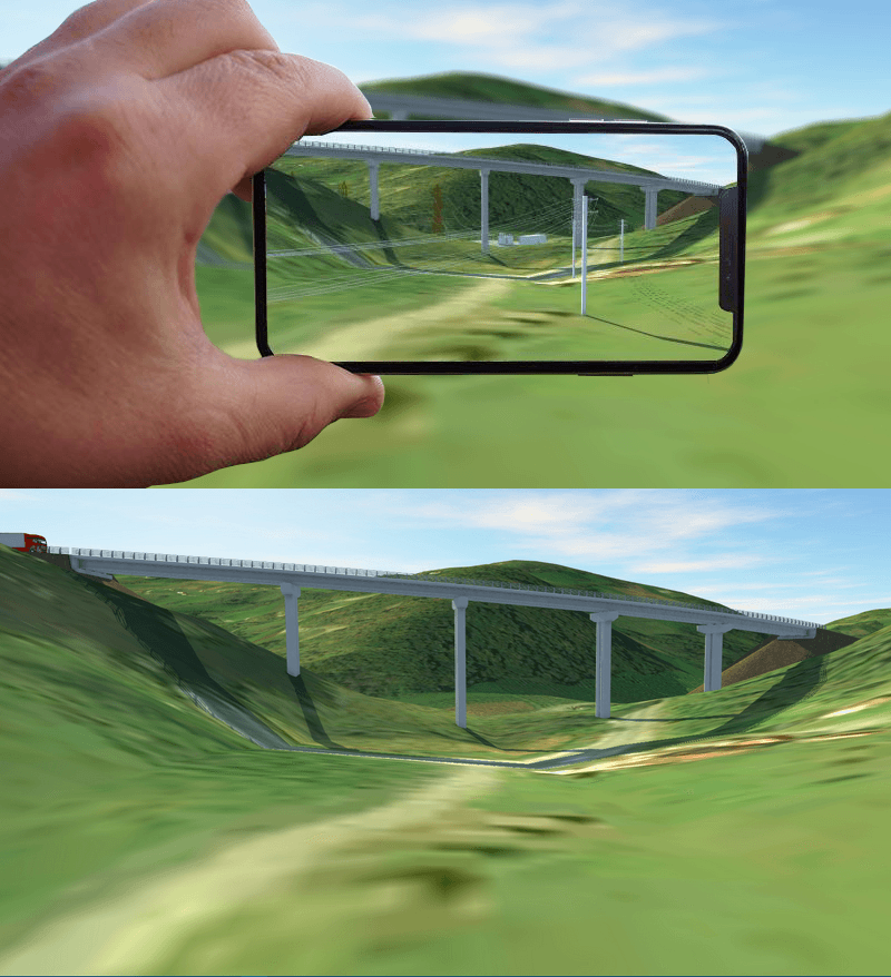
- Cost savings are based on the implementation and use of this technology. For engineers with basic project development needs, it accelerates the design process and simultaneously explains what BIM is. For engineers with advanced needs, it automatically generates BIM facilities allowing the model to be used for: visualization, AR (Augmented Reality) and the following construction phases (4D, 5D, 6D).
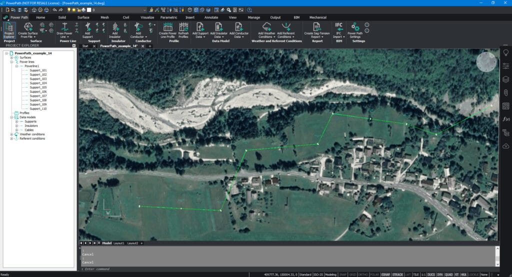
This is how the project of overhead power line created with Power Path solution looks:
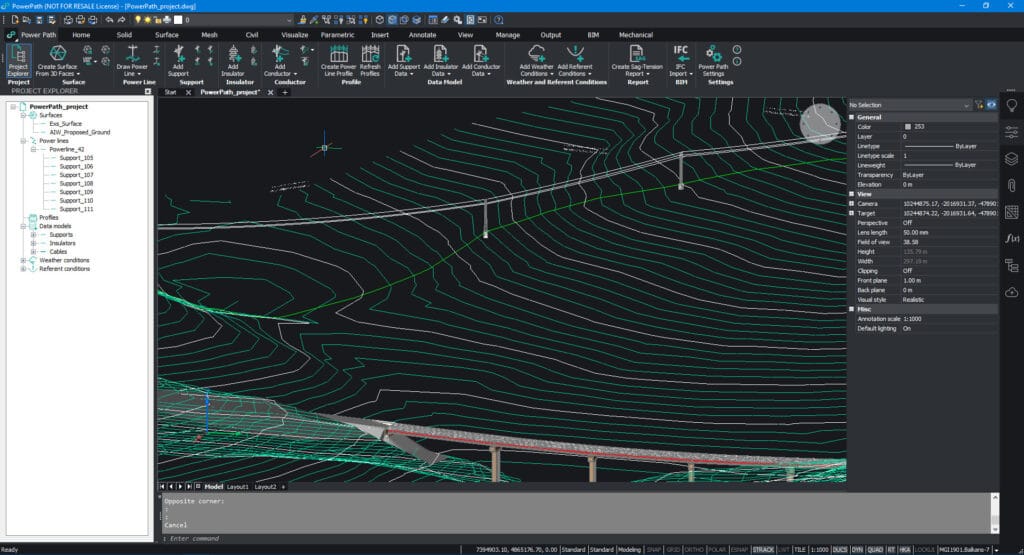
In the planning and designing phase users have 2D and automatically 3D created power lines with metadata:
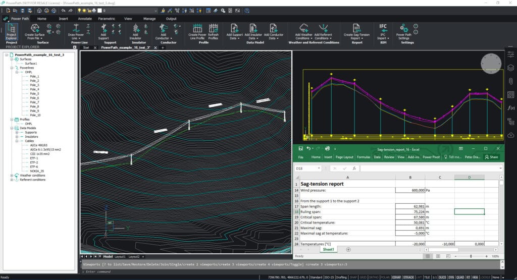
Calculations are also implemented in the solution:
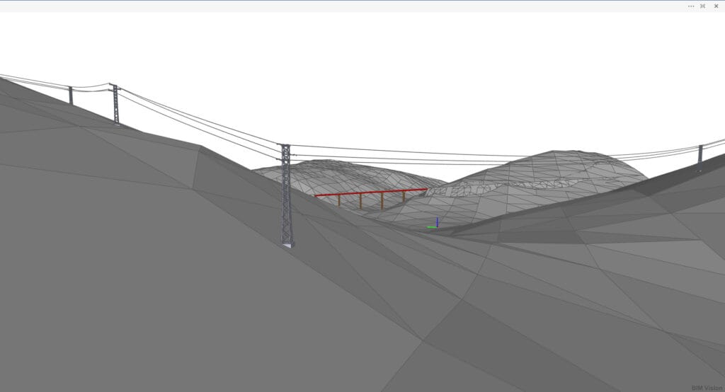
For the construction and management phase digital record of the power line enriched with BIM information can be used on site:
More about Power Path read in blog posts or subscribe to the Power Path blog.
If you want to create your own OHL project with the BIM approach, try 30 days free trial of Power Path.
